Copper cables are finding their use only on the top-rack connection and are being replaced with optical fiber networks to enable cost-effective migration of data centers to 40G and 100G or even higher. Along with the higher speed, durability as well as exciting opportunities, a certain degree of complexity also creeps into the structure of data center when Ethernet applications are put to use to meet the objectives. Though all the complexities are well taken care of, but there are certain challenges that lay covered and show their ugly results when the data center is under pressure to deliver 100% uptime or extended reach. Of these complexities, reflectance of connection is one such issue that may cause downtime leading to network failure that creates havoc at the ultimate users’ end.
Connection Reflectance – main causes and solution
Migrating to 100G networks by choosing a 25G line rate, in the group of 4, calls for the use of a dedicated optical transceiver. This gives rise to discussion if the present standards for multimode fibers (ISO/IEC 11801 2010; TIA-568.3D 2013) and single mode fibers (TIA-568.3-D 2013, ballot 6) are adequate or not. Presently, reflectance of -20dB and -35dB are set for these fiber types. So, to solve the reflectance on SMF in a 100G or 400G network, it is suggested to enhance the standard from -35dB to -40dB/-45dB. This increase can be of great help with 100GBASE QSFP28 transceiver from Cozlink and also with 4x25G kind of arrangement. In the latter, the parallel optics comes into play and gives rise to connection reflectance as MPO connectors are attached to the transmitter directly via a fiber patch panel. This brings constant change in permanent link, a typical situation in high-density networks. In order to bring fiber patch panel into action, it is ideal to use ribbon style fibers that help in quicker and faster installations.
MPO connector and its repeated connecting and disconnecting with various network points are unavoidable situation in a flexible, high-speed data center network. This network limitation is responsible for MPO connector enabled reflectance that arises due to poor contact because of this. To address the connectivity issues caused by poor contact, the use of UPC endfaces and APC endfaces are recommended for single mode and multi-mode fiber networks respectively.
Testing is a proactive way to address reflectance issues and it is being modified
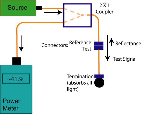
OLTS (Optical Loss Test Sets) constitute the common testing method adopted for finding transmission loss per specific application. It can provide bi-directional testing in less than 3 seconds on any given two wavelengths. The testing method is encircled flux compliant and is modified as per the prevalent conditions such as portion going to the connector in comparison with the fiber, loss budget shrinkage.
Results of the testing methods suggest that in a multimode fiber set up, connector and fiber mismatch is an important reason for reflectance. It leads to fiber link loss due to under filling of the core with optical lightwave, and also due to over-filling caused by LED that estimates the losses incorrectly. Overestimating or underestimating the fiber link loss is a major setback to the correct working of a high-speed data center, to combat this situation, an Encircled Flux principle based light source is recommended to carry out the testing procedures. Many of the companies ignore the importance of testing and are forced to take the products off the shelves in the long run.
OLTS is effective in detecting the fiber link loss, but it does not pinpoint the exact source of the loss, or the exact point of fault in a connector. It also cannot determine the measure of loss happening at the connector end. So, to make the loss testing more fruitful, OTDR procedure compliant with Encircled Flux method is considered to be the better option. It can measure the reflectance at each connector in the link, can determine the position of fault in all I/O connectors and also determines the localized insertion loss. Thus, there is no requirement to topple the whole of the network in case of failure and the restoration also becomes faster, as the managers need not check the whole network for detecting the loss.
Contamination – another source of link loss in a high-speed data center network
Connector contamination is a big issue arising from simply unavoidable situation. It occurs mainly during installation when the installer fits the connections and in the process transfers the oil from the hands to the connector. The return loss may increase from 10dB to 12dB in case of single-mode fiber. And it becomes more significant in high speed migrations where 25G or 50G connections are established.
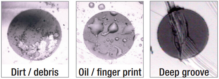
Thus, use of fiberscope to detect dirt and oil is the wise practice and it should be carried out at every instance of insertion and reconnection. Avoiding it may wreak havoc on the uptime failing the purpose of the high speed migration completely.
To conclude, with the increase in expectations from data center performance, it has become imperative to revise the ways the networks are being designed and tested. The existing techniques of installation, testing and performance evaluation were meant only for 10G connections; thus, while moving to higher speeds, the application of more accurate, faster and more sophisticated testing procedures is necessary. Just installing a 25G device will not serve the purpose; change is required at every aspect of upgradation and expansion. So, the sooner the loopholes and their solutions are recognized, better for the long life of the network.