Ever bought yourself a pair of headphones that have a non-removable cable which is heavy and annoying. Or maybe you have a favourite pair of headphones but you can’t use them any more because the cable broke from when you accidentally stood up and pulled the cable too hard, or snagged it on something. Well there is something you can do to fix that. It’s so simple and such a great idea that you will think to yourself, “Why don’t they do this to all the headphones on the market”, and if you think that, then you are smarter than you look. JK, JK. Jokes aside, this mod is a complete possibility for most headphones. Of course, there are number of things you need to first realise if the mod is viable or worth doing for your current headphones. These things are:
- Do you still have warranty, and are you going to risk parting with that warranty.
- You have to be aware that modifying anything has a huge risk of you damaging it beyond repair.
- Dismantling your headphones sometimes requires you to glue it back together, this depends on the construction of them. So you need to be aware that gluing might ruin the aesthetics of your beautiful looking headphones. This also includes scratches, cracks and chips when prying it open.
In case you don’t know what I’m talking about, I’ll show you what I mean. These are 2 pictures of the Audio-Technica ATH-M50 headphones (first photo is a removable cable mod, second photo is the stock headphones with the OEM cable):
Removable Cable
Now that we’re on the same page, we can continue.
There are a few advantages that you will inherit after doing this mod:
- The headphones become more portable.
- You get the flexibility of choosing the cable length, grade and style.
- Lifespan of your headphones greatly is increased because, in most cases, the first component to fail on any headphones is the cable.
- Depending on the OEM cable, you can switch out for a much lighter cable.
- Flexibility to make your own DIY cables for more satisfaction. This includes making a cable with an inline mic for use with a smartphone.
- The value of your headphones is increased. A buyer would pay more for headphones with this mod because of the advantage outlined here.
- And of course, the overall satisfaction and pride knowing that you did this all on your own and you can truly say that your headphones are “yours”.
Before you begin!
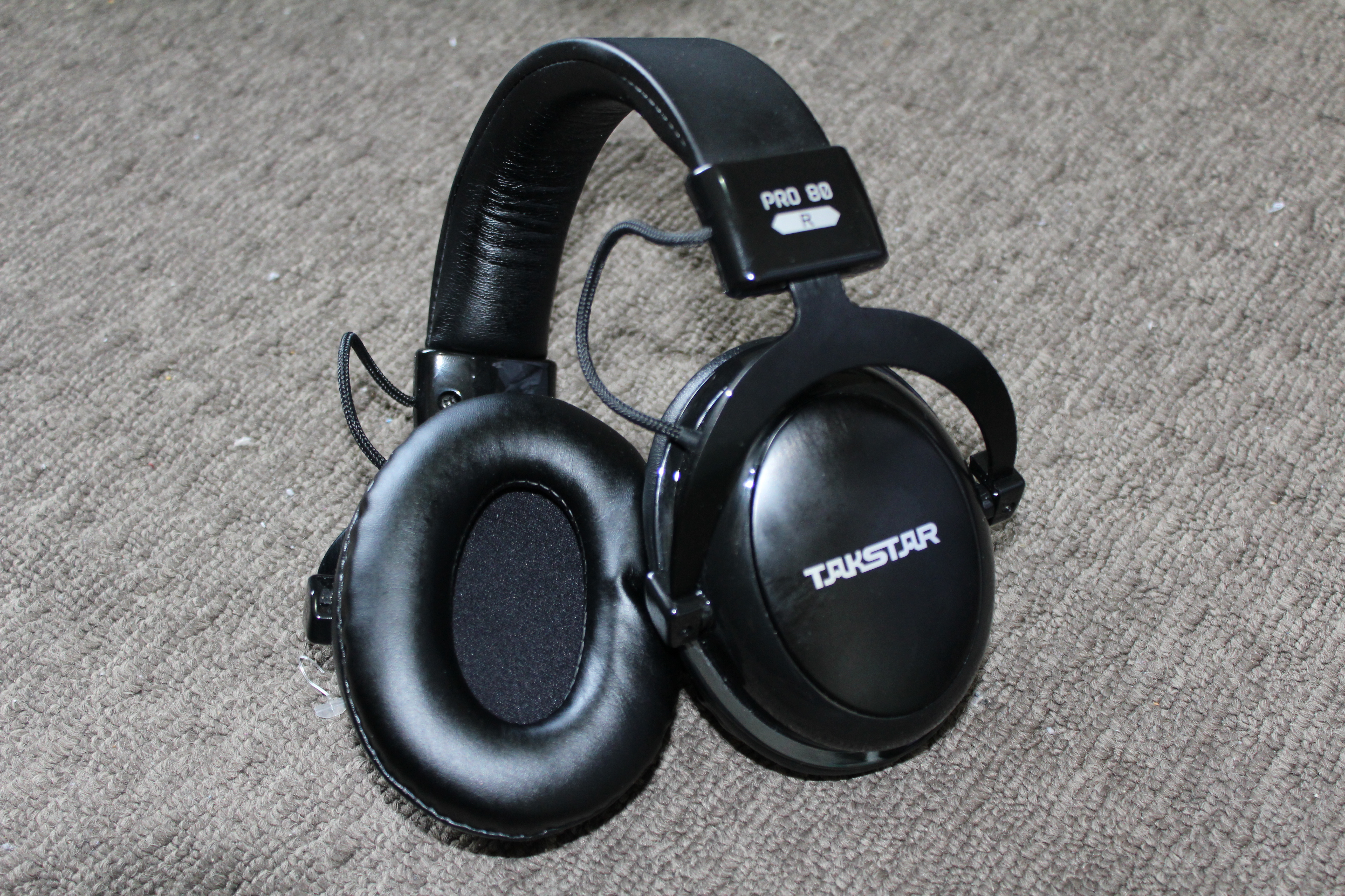
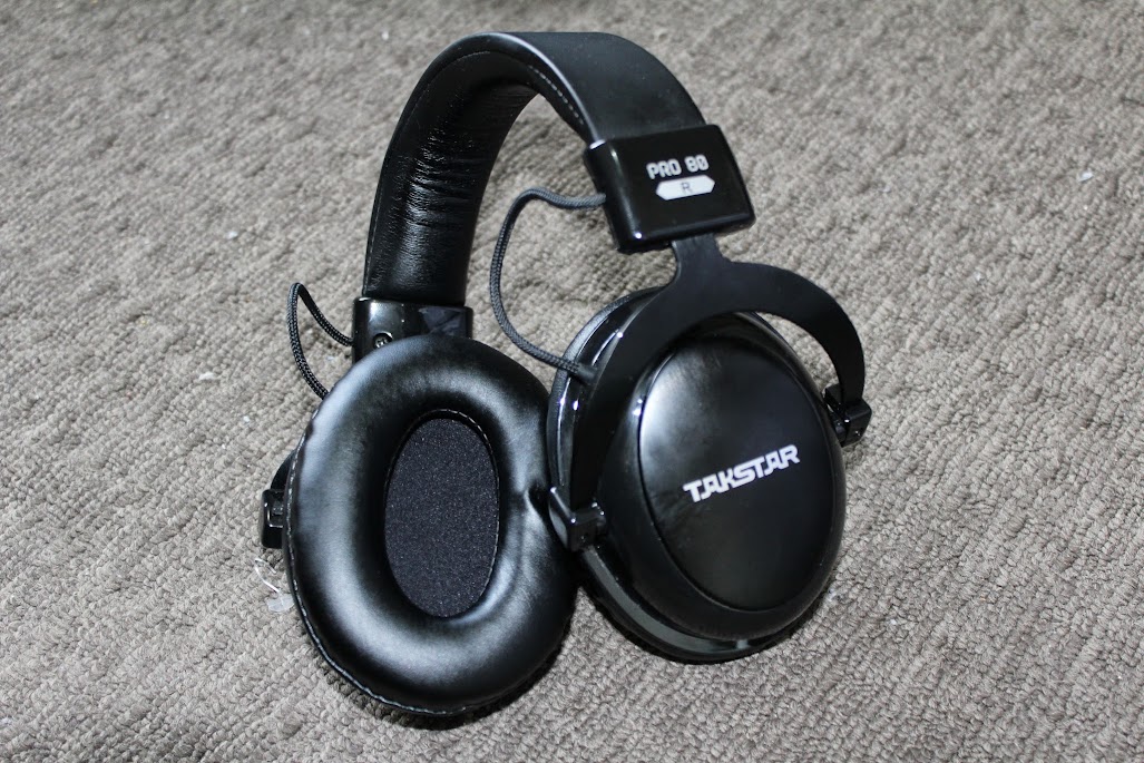
Throughout this guide you’ll see images of my Takstar Pro 80 headphones I got for AU$60 on eBay. I modified them myself without a guide. Hence I made this to help others thinking of doing the same thing.
Before we get ahead of ourselves, you now need to sit down and ask yourself, “Can I do this?”. Of course you can, anyone can do this. But before you start ripping you headphones apart you need to know how to solder. Here is a couple of links to some good soldering tutorials I used to learn to solder: Tutorial 1 | Tutorial 2 | Tutorial 3. Make sure to practice a bit to make sure that you are competent and confident in your soldering technique. Try to keep your solder joints (connections) small because you’ll be soldering small connectors and thin wires. The less naked wire you have sticking out, the small chance of anything going wrong inside.
Now that you’ve learnt how to solder and you are confident, you now need to go onto Google or your favourite search engine and trawl the internet to see if anyone has already disassembled your model headphones. This will be VERY helpful to you, because you greatly lower the risk of damaging anything in your precious headphones.
Next step, as I like to call it, is exploration surgery. You need to disassemble you headphones and see how much room you are working with inside the cup under the driver (speaker) housing. Some headphones will just come apart when taking apart screws, others will need to be cut open with a knife at the joints if they are glued together or using steam or a hair dyer to soften the glue. The typical sequence will go like this:
- Take the cushion off.
- Search for screws on the housing.
- Take said screws out with a suitable screw driver
- Be very careful when taking apart the housing making sure you don’t pull any wires out in the process.
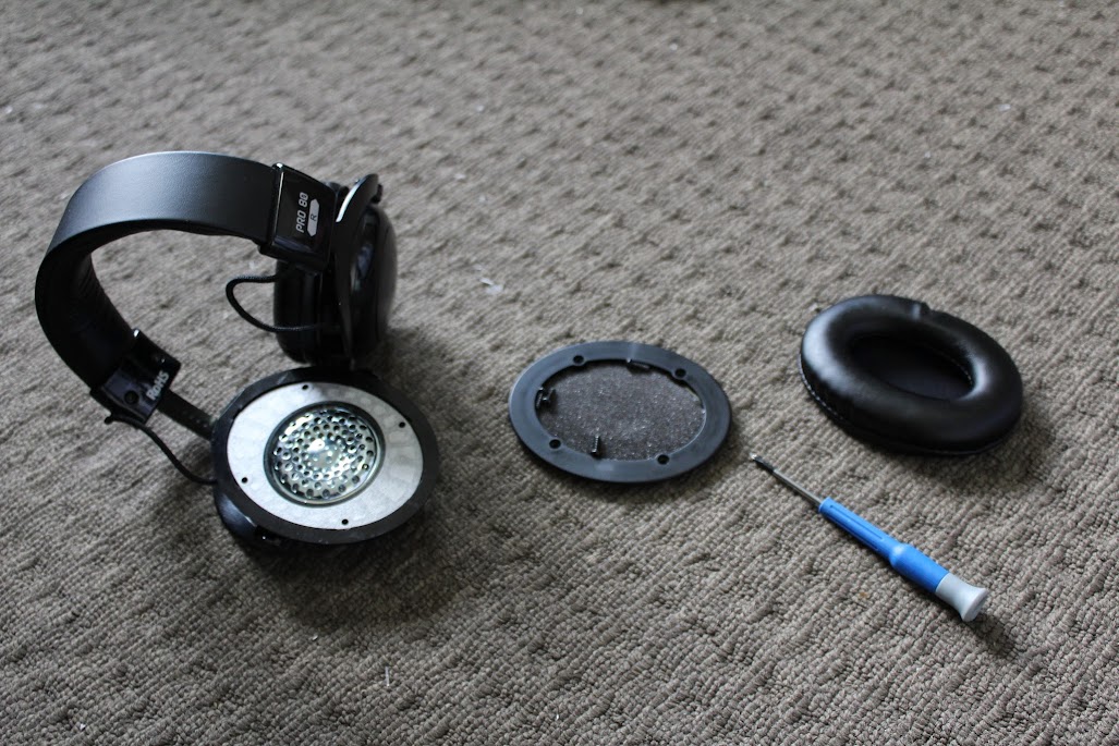
Have a good look at what you’re working with inside and try to visualize where the 3.5mm chassis socket is going to go. It is super important that the 3.5mm socket that you’ll be installing will fit inside. In the photo is the headphone cup opened and showing the 3.5mm socket I have installed. This is to show approximately how much room is required in the cup for this mod. Different headphones will have different designs, drivers, dampening materials and overall space inside the cup. This is why you’ll need to open them and explore your options.
3.5mm chassis socket with mounting nut.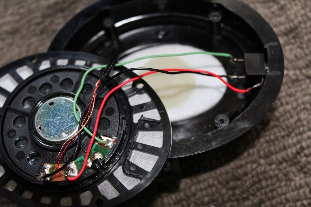
Getting Everything Together!
If you’re happy with the space inside the cup. You can start getting all you tools and components ready. You should already know what you need from you exploration surgery, but here is a check list just in case:
- A soldering gun or iron. Any iron would do as long as it can do about 650-700 degrees Celsius.
- Some solder. You won’t need much and it goes for very cheap. Any type of solder would be. I used 50/50 solder because I already have it. Some would swear by only using 60/40. Other enthusiast use only use silver solder. 50/50 is perfectly fine with copper cables and won’t be noticeable, regardless of what people say.
- Screw drivers. Size and type of screw driver depends on what type of screws are used on your headphones.
- Needle nose pliers.
- Wire cutters.
- Wire stripper or just a knife. I have always used a knife to strip the insulation from wires.
- Wire. Some headphones won’t need extra wire but it’s good to have just in case. I use CAT5 cable (Ethernet cable). They have multiple strands that are absolutely perfect for audio applications. Why not use the wire we trust so much to bring the world wide web to us?
- a 3.5mm chassis socket. Make sure it’s a stereo 3-way connector socket. (i.e. left/right/ground or tip/ring/sleeve)
- A drill or rotary tool. If you need to drill an extra hole because the OEM cable hole is too close to the wall and your 3.5mm socket doesn’t fit or whatever reason. Hopefully you won’t need to do this.
- Hot glue or just your everyday super glue. In the case that you headphones need to be glued back together or you need to glue anything for any reason.
- And lastly, please make sure that you have a 3.5mm male to male patch cable before doing this mod. Other wise you won’t be able to use your headphones. I made my own patch cable.
Jumping in the Deep End!
You should already know how to take you headphones apart:
- Disassemble your headphones.
- Using you wire cutters you need to cut the OEM cable underneath the knot or near the rubber grommet that holds the cable to the cup/housing.
- Pull the OEM cable out and put aside (you can buy a 3.5mm jack and restore you OEM cable as a patch cable for you headphones).
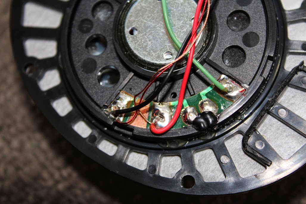
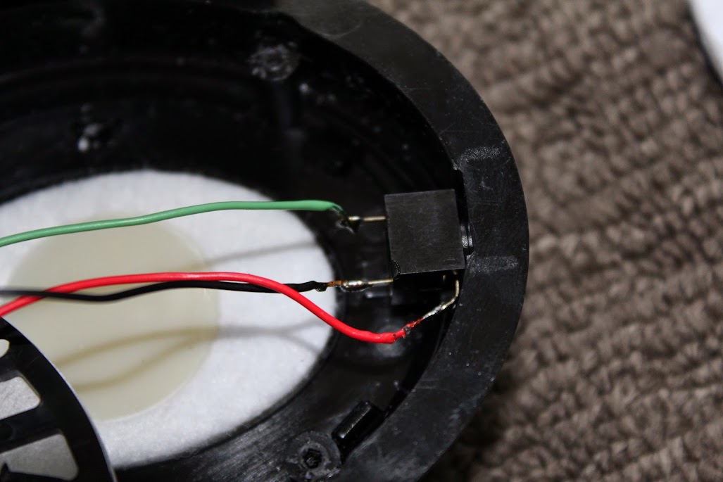
- Undo the knot and remove the outer insulation from the rest of the cable and you should have 3 separate smaller wires. They will be left ear, right ear and ground. In my headphones the black wire is right channel, red is ground and green was left. I worked this out by looking at the way it was wired together. Looking at the picture below, you’ll notice that there are 3 thick wires that go to the OEM cable and 2 thin wires going into the headband, spanning across to the right ear cup. What this tells me that the terminals were the 2 small wires are for the right driver. But to find the ground without a multimeter is trickier. If you look at the little PCB, you’ll notice the the terminal where the red wire is connected has a bridge that goes across to the green wire. What this tells me is that the red wire is ground because it is shared by both channels. Needless to say, your headphones will most probably be different, and using this kind of logic, you can figure it out.
Wiring. - It is a good idea to leave these wires connected to the driver and solder them onto your 3.5mm socket, as I did. This is because some drivers are sensitive to heat and can burn out if your soldering iron over heats them. So using the left over of the OEM cables to solder to your 3.5mm socket will save you from this risk.
- Now you need to make sure that your 3.5mm socket will fit in the housing. Put the 3.5mm chassis socket where you want it to go and fix in place, and see if the cup and housing will come together without any interference. If there are unnecessary bits of plastic coming out for what ever reason (it maybe to hold the OEM cable in place) you’ll need to remove this with care to make room. Don’t remove any mounting points for screws or anything that is electronic. If you cannot get the 3.5mm socket to fit you may need to drill a hole somewhere else in the cup to suit the 3.5mm socket. Be strategic about placement.
My headphones had 2 plastic webs or walls which I needed to remove. I used the wire cutters to snip them off and the 3.5mm socket fit perfectly. - If your headphones have any dampening material inside, you may need to use some scissors to cut a rebate out for your 3.5mm socket. DO NOT throw away the dampening material. It is there for a reason. So please put it back where you found it before you reassemble you headphones. They improve the overall sound quality and sound insulation of the headphones.
- Once you are happy with where your socket is going to go and you are confident that the headphones should close back up without any interference, we can continue to the soldering.
- You’ll need to strip the insulation from the wires on the leftover OEM cable, expose only about 5mm of the copper strands. Twist them off and “tin” the tips of the wires (as you’ve learnt in the soldering tutorials). Next you need to solder these wires to their corresponding terminals on the 3.5mm chassis socket. (tip=left, right=right, sleeve=ground).
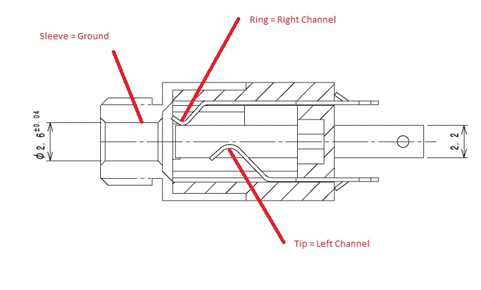
3.5mm Socket Diagram Make sure your soldering joints are not huge to prevent any shorts inside your headphones if you accidentally drop them or anything like that.
Solder Joints. - Test that everything works.
Wait about 30 seconds for the solder joints to cool down. Plug your 3.5mm male to male patch cable into the socket and into your audio source. A PC is a good way to test because it has a built-in stereo checking function. Run the test to make sure that you have the correct channels on their corrects sides.
Testing! - Troubleshooting. (These things that may go wrong are only if you really messed up during the whole process, like yanking on wire too hard or making you solder joints too large and/or soldering and wires are bridging and shorting each other):
a) If you don’t have any sound in both drivers check the volume first. If it still doesn’t work this means that you either have a short somewhere, your ground wire in not connected in the right place, or you have a broken wire. Check your wires, make sure they are all connected to their respective terminals if you know they are, then it’s possible that your wires have broken in the process. Change out the wires for some CAT5 wires. Repeat the soldering process but this time you’ll also need to solder the wires to the terminals on the driver. Be sure not to keep you iron on those terminals for too long because you can burn out the drivers (if you soldering iron is rated to over 1000 degrees Celsius, then I suggest you do not do it until you get one that is rated to 650-700 degrees Celsius).
b) If only one speaker works then, repeat same troubleshooting as above but only for that speaker. Making sure that the ground and hot wire are connected properly and that there is no short or a break in the wire.
c) If your sound is mono then this means the you have shorted the 2 hot (left and right) wires together. Both channels will cross over each other.
d) If you tried everything and you can’t get the driver/s to work, then you should probably start saving for a new pair of headphones. Bad luck, try again. - Screw the socket into place with the mounting nut that comes with the socket. Alternatively, you can glue it in place. I personally hate glue so mine is just screw into place. Tightened with the need nose pliers.
- Reassemble you headphones to their original state, and marvel in your own excellence! Congratulations, you are now an honorary DIY’er.
Marvel in your own excellence!


NOTE1: You might have seen a similar post on Head-Fi Forum. Yes, that is my post too. I thought I would do a more universal and in depth guide here on our blog. If you like my tutorial, please jump on Head-Fi Forum and give some support. Thread here!
NOTE2: Any damage caused while doing this is not my responsibility and the fault is completely on yourself. I’m simply showing you a guide. You’ve been warned more than once.
![[DIY] Headphone removable cable mod](https://technofaq.org/wp-content/uploads/2014/04/File-permissions-e1397818633361-150x150.jpg)
![[DIY] Headphone removable cable mod](https://technofaq.org/wp-content/uploads/2014/04/ozobot-150x150.jpg)
13 Comments
Carlos
20 April, 2014Thanks Bro you help me a lot, i used philips headphones and work pretty fine so thank you so much
(im brazilian)
Igor Rebenko
20 April, 2014@Carlos
No worries mate! Have you got any pictures to show? =D
Carlos
20 April, 2014im so sorry 🙁 my philips headphone broke and i cant fix it beacouse de iron burned the speaker and broked:( but i bought another headphone (not philips) and i got a problem and i need your help
thank you
Carlos
Carlos
20 April, 2014hey its me again 🙂 I made other headphone and work pretty fine thank you so much to helping me and others want to now how to do this, so thank you so much @IgorRebenko!!! 🙂
I will send a photo of my headphone to you later
bye
-Carlos
Igor Rebenko
20 April, 2014Hey mate!
Sorry I didn’t reply to you earlier query. I’m glad you got it working. And thanks for the encouragement.
What headphones did you buy?
Carlos
20 April, 2014Hey @Igor Rebenko sorry to awnser to you too late but, i got a super market headphone really cheap but incredible sound and bass im so glad that is working thanks for this tutorial 🙂 i used the first connector but they let the cable fall out and i desasemble a sony recorder and get the audio output and work much better and dont fall out the cable any more, SO MUCH THANK YOU AND THIS IS THE BEST TUTORIAL I EVER SEEN SO THANKS @Igor Rebenko
PS: i cant (and dont now) send photos because im trying to find my solder hehehe
bye
-Carlos
sunny
20 April, 2014hi igor, was wondering if it were possible to change a 2.5mm chassis socket within the headphones to a 3.5 socket. ive got sol republics (i know its frowned upon in audiophile world) and want to switch the socket to 3.5mm. i also want to make a 3.5mm (stereo) to 2 x 3.5mm (mono) jack, but not sure what cable to use. would the canare quad star suffice?
Igor Rebenko
20 April, 2014Hey Sunny,
It is possible, absolutely! You may need to modify the cups a bit and you’ll need to find a very small chassis socket. Canare is a great cable, you can also get some good cable on eBay for pretty cheap; cables that are OFC, Lits, SPC, and more. Have a look around. Also, Aliexpress is good to find this cables and components for cheap.
Ross walker
20 April, 2014Are these the same as the HI2050’s except they are closed? I want to mod mine so that i can use a V-Moda BoomPro, i already have the headphones, microphone, and the chasis socket and i have everything else you have said in the list, is everything the same inside these so i can just read/look at the pictures?
Igor Rebenko
20 April, 2014Hey Ross,
It is structurally the same. But the internal padding is slightly different. The steps to do this mod should be the same. Just visually different obviously.
Have fun!
Goeshman
20 April, 2014Hi Igor, thanks for the tutorial
Thinking to do the same with my HI2050, but i’m having trouble to find that 3.5mm 3 pin chassis socket for stereo because all are telling me that they are mono. But i do an alternative like this http://www.ebay.ie/itm/3-5mm-Mini-Stereo-Jack-Chassis-Panel-Mount-Headphone-Input-Socket-Connector-/351816396013?hash=item51e9e42ced:g:KBYAAOSw9N1Vjo~U#shpCntId
(need to order it from UK, coz they pretty hard to find in my country) but i dont know if it would fit.
TIA
Josh
20 April, 2014My headphones have RGB lighting. If I do this customization/soldering, would the RGB lighting still work?
Derek
20 April, 2014FYI, Some of your photos are not showing. Great article, thanks!